Grounding Quality: Not Just for Audiophiles
How and why does the grounding potential influence our audio system and how to improve it.
A Few Words on Human Hearing
The most sensitive human sense is hearing: it has an unbelievable resolution of one billionth, a millionth of a millionth – twelve decimal places. Although good quality audio devices include power filters, some outer interference will still get to the signal path, from the amplifier to the speakers and to our sensitive ears.
How can we hear high frequencies?
High frequencies from the power grid get to our audio devices through their power sources. We do not hear these high frequencies, we hear their alterations. Imagine digital packets (or noises) 1 ms far from each other: we will hear 1 kHz. If, in a 230 VAC power network, there is induced a high frequency component of only 1 mV, it will certainly get to the power supply part. Add attenuation of 1000 of the power source part and power filter; we now have 1 μV in the power, one millionth. Our hearing is, however, more precise; by another six decimal places.
Powering from the Power Grid
We all power our devices from a common network, a power grid, and each electrical appliance contributes its own share of interference into it. All devices should comply with EMC standards which define borders of allowed electromagnetic emissions. However, in the modern times of switched-mode power supplies and frequency converters, interference in the power grid is much stronger than it was years ago. Manufacturers are generally pressed to integrate filters into their devices, the quest of which is to limit the emissions. The more effective the filter, the more expensive the product—and therefore less competitive. That is why its emissions balance on the bear limit of the EMC standards.
How Filters Work
We will not go into technical details of different types of filters. Generally, a filter are tailored to fit a specific device, so that its working area has its largest efficiency exactly where it is needed.
Expressions used further:
L – phase, in Europe 230 V/50 Hz
N – neutral conductor
PE – protective conductor (or ground/earth)
HF – high frequency
Wiring inside a Simple Power Filter
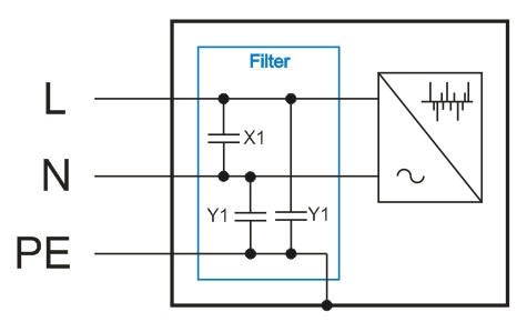
Skipping the details, standardly, the simplest filters use capacitors with a dielectric X1 between L and N, complemented by capacitors Y1 between L and PE and between N and PE. As a general rule, connected to the grounding PE, there is also shielding or the outer housing of the device, which conducts other HF components onto the PE and into the ground.
Leakage Current (IL)
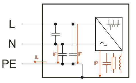
is the electric current that goes through PE to the ground. It is a sum of currents IF from internal filters of the device and current IP that occurs between isolated parts of the device due to internal capacitances and inductances inside the device.
The largest share of leakage current is attributable to the aforementioned filters (IF). They lead high frequency interference from devices to the PE conductor.
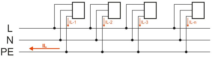
The shares of all devices are added and go to the ground through PE. All devices connected to any phase contribute to leakage current as the PE conductor is common for all phases.
Earthing and Connection Arrangements
Today, several types of network and voltage system arrangements exist. We are going to limit our scope to two that are used at home. TN marks a network in which one point is directly grounded and parts of the device that are not live are connected to this point.
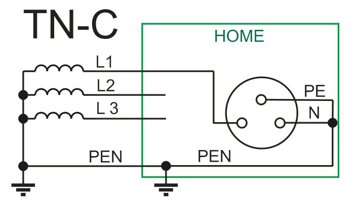
TN-C
These older, usually aluminium assemblies with only two conductors are uncomplying today, both from the point of view of safety and hifi: the audio system “doesn’t have a proper ground.” If a grounding pin is connected to N in a socket, all HF interference components get to PE right away as well. Due to current and parasitic resistance, there is also a drop in voltage. Shielding of audio devices connected to such network ceases to be shielding because all HF interference from N is lead to it.
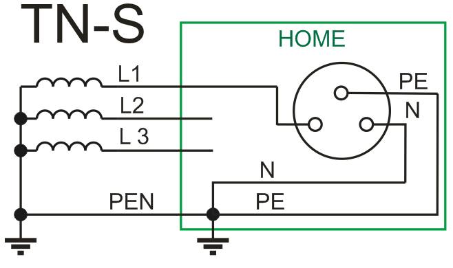
TN-S
This TN network has PE and N separated all the way from the grounding point.
New TN-S home assemblies are much better. All current is lead through L and N, including HF interference components. PE then serves as, for one, protection from dangerous contact voltage in case of a defect, but it also leads leakage currents of individual devices. The leakage currents are then lead to a common grounding point in the main switchboard.
Grounding Quality
is frequently underestimated. Earthing resistance is of course being measured with newly built houses, but it is rarely the case with buildings that are decades old. Soil moisture, oxidation of contacts or loosened screws all have essential effect on its quality.
Functions of Grounding
An earthing system unifies the common potential of all non-live conductive parts, giving it the potential of earth surface. As such, it provides protection from electric shock, lightning strike and overvoltage. The PE protective earth conductor also leads HF components from filters of most appliances, as was mentioned. In order for these HF components to be lead away effectively, grounding resistance has to be as small as possible. The same goes for effectivity of protection against shock and lightning.
Electrical resistance of grounding (RE) is determined by measuring the resistance between earth surface and connecting (earthing/grounding) point of a building. The value is dependent on the type and humidity of soil, number and quality of grounding points, etc.
How to measure grounding resistance and what value should it be?
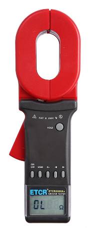
With houses, it should be less than 5 Ω, in unfavourable conditions 15 Ω. The measuring has to be done by an inspecting technician using electrodes in the ground or by a newer induction method using a clamp meter.
Types of soil and their resistance
| Type of soil | Resistance Ωm |
| Peat | 30 |
| Topsoil | 100 |
| Damp sand | 200–300 |
| Damp gravel | 300–500 |
| Dry sand or gravel | 1000–3000 |
| Dry stony ground | 3000–10000 |
Soil/ground resistance is very much dependent on humidity. Surface humidity changes to the depth of about two metres, further on it is stable.
How to Improve Quality of an Existing Grounding (not just for Audiophiles)
Although the allowed boundary is less than 5 Ω, the ideal resistance is as small as possible. Less than 1 Ω is the ideal of every audiophile. Unfortunately, such values are not reasonably achievable in bad soil conditions. Earthing rods are hammered 20–30 cm underneath the ground level and are linked by a thick grounding wire or bars. All joints must be covered in asphalt or with another protective layer.
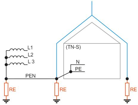
In all soil conditions, grounding resistance values can be significantly improved by using additional earthing rods. Resistance of one rod R=0.9 * ρ / L , where ρ is resistivity of given soil a L is length of an earthing rod in metres. The rods are, ideally, placed in a star shape going from the common grounding point 2 to 3 metres far from each other. The final grounding resistivity is then an addition of their inverse values.
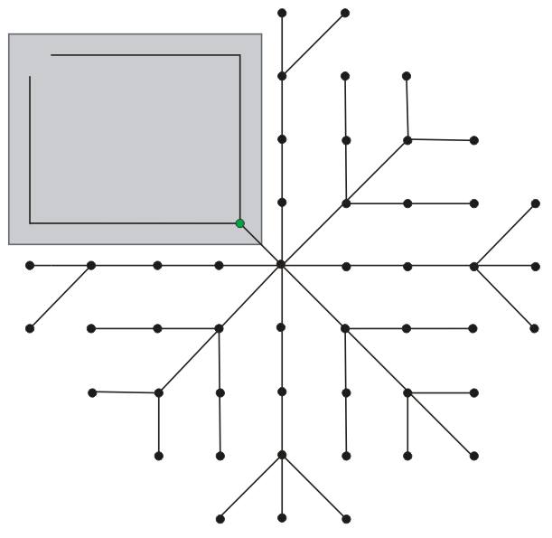
In the image below, there is a ground plan of a building. It should have grounding bars under the foundations, which then lead to the common grounding point (green). Lightning rod and PEN conductors should also lead here (with TN-S, PE leads here, N to the main switchboard).
Price for Grounding – Extreme Example
Price is mainly dependent on the span of the entire grounding and the number of earthing rods. One average 2 m galvanised earthing rod costs about 20 €, a copper version 200 €. A 1.5 m T-shaped earthing rod is about 10 €.
Example
Damp stony ground with resistance of ρ=250 Ω/m
R=0.9 * ρ / L
R=0.9 * 250 / 2 = 112.5 Ω. One earthing rod hammered in this very bad soil will have a value of approximately 112 Ω.
In the image above, there are 48 earthing rods in a star-shaped arrangement. To make the count easier, let us imagine the same ground resistance (112 Ω) on all the rods. The final resistance of this grounding system will be RE=R/N = 112/48 = 2.3 Ω. In reality, the outcome will be even a bit better because the old grounding underneath the house foundations will be added to the new additional system.
The price of 48 2m rods is about a 1000 €, add material to connect these and work.
Are you building a new house and want the best grounding resistance?
Put earthing rods 2 to 3 metres next to each other into the excavated foundation strips, the deeper the better. Connect the rods with grounding bars. Lead the bars from the main grounding point in a star shape to individual earthing rods. Never close the bar loop. Cover any bolted joints in asphalt and pour concrete over the assembly, onto which isolation and the baseplate will go.
It is also desired to have additional grounding going from the grounding point into the garden. Hammer the earthing rods as deep as possible according to the soil quality, ideally 2 metres deep. Once again connect them in a star-shaped way going to the common grounding point. The maximum reasonable size of the assembly from the grounding point is 20 to 25 m.

Do you want to go even further?
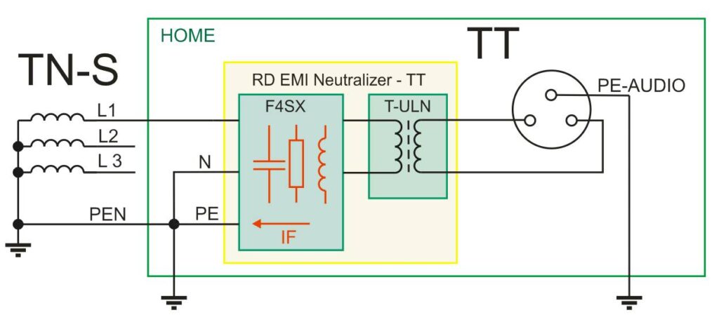
Create your own TT circuit and completely disconnect your audio system from the rest of the network. TT circuit has its own grounding point. Its quality and distance from other grounding points is also important. Using a special version of RD EMI Neutralizer with a TT design, you can completely isolate your audio system from the network and the common PE. Effective EMI filter F4SX leads HF interference to the PE conductor of the home network. Isolation transformers T-ULN separate the DC direct current component and the remains of interference. The audio system is then powered by even cleaner voltage with its own grounding point. The grounding point of PE-AUDIO once again has to be of appropriate quality, ideally less than 1 Ω.
What to do with the quality of an existing home network?
1) Get a good power filter, like RD EMI Neutralizer, and completely separate your audio system from the common network.
2) Verify the quality of the main grounding point (inspecting technician), possibly improve quality of the grounding.
3) If you have additionally connected shielding complementing your audio components, using an ohm meter, make sure that the shielding of any of the components is not connected to PE. If it is, do not use additional shielding; it causes unwanted ground loops.
4) Lead the power to the components from one point in a star-shaped arrangement, like RD EMI Neutralizer does.
5) Measure the impedance of the current loop (inspecting technician).
6) Power the audio system from the cleanest phase available (as a rule, three phases are lead to a house and a given socket circuit can be easily switched in the main switchboard).
7) For an audio system, the ideal situation is a separate electrical circuit and cables going directly from the main switchboard where the grounding point of the building is connected.
8) Improve the quality of the grounding point.
A Final Note
This article is intended to give the reader an outlook on the issues of grounding and its link to high frequency interference—how can it influence an audio system, why is it important and why more and more interference exists in the network. But what about the significant HF interference that exists between phases L and the conductor N?
Interference consists of both symmetrical and unsymmetrical components that a good filter can effectively suppress. That is what we base on the recommendation of RD EMI Neutralizer with galvanically separated T-ULN transformers as the cornerstone of any quality audio system.
Newsletter
We'll let you know about our participation in audio shows, new reviews and products, new places to listen to your speakers, or new posts on our blog. We won't spam you.