F4SX Audio Power Filter
In this article, you will learn why a good audio power filter is essential these days, why we use latest nanocrystalline materials, how does a passive power filter help in audio and more.
A Tad Bit of Physics
The 19th century has brought a myriad of findings in the field of electricity. Before Nikola Tesla invented the electric engine and Graham Bell the telephone, in 1831, Michael Faraday described electromagnetic induction and so laid a foundation for the entire field of electrical engineering. Electromagnetic induction denotes a phenomenon when magnetic field occurs around a conductor due to current that flows through it.
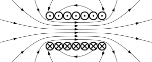
Permeability
Magnetic field can be transferred using magnetically conductive materials. Permeability then is a kind of material constant the value of which depends also on other parameters, such as the size of the magnetic field, frequency, hysteresis, and others. Depending on permeability, we divide materials to paramagnetic materials and feromagnetic materials where μr is several times larger than 1. The race for the best magnetically conductive material could start. It was found that various alloys achieve higher permeability than iron or steel.
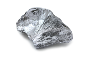
Molybden
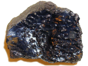
Iron ore
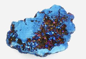
Cobalt
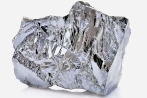
Nickel
Permalloy
Invented in 1914 by physicist Gustav Elmen at Bell Telephone Laboratories, permalloy is an alloy consisting of approximately 80 % nickel a 20 % iron. Permalloy generally achieves about 100x higher permeability compared to iron or steel. Supermalloy followed in 1948 as an alloy of 79 % Ni, 16 % Fe, and 5 % Mo.
| Material | Permeability μr |
|---|---|
| Supermalloy | 100 000–900 000 |
| Permalloy | 50 000–140 000 |
| Iron | 300–10 000 |
| Aluminium | 1,000 023 |
| Copper | 0,999 990 |
| Oxygen | 0,999 990 |
The Present
Today, using complex simulation and thanks to developments in material engineering and superior manufacturing processes, nanocrystalline materials are used. Thousands of alloys with various specific properties are available. The range of magnetically conductive cores available is vast but as is usually the case in life, an absolute ideal for every use case is non-existent. One needs to find and test the most fitting material that will achieve the needed magnetic field intensity, it will be effective on the required frequencies, and will be accessible price-wise.
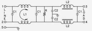
F4SX Power Filter
Our filter cleverly combines four filtration sections, which are designed to filter symmetrical and assymetrical interference in a wide frequency spectrum. The filter also includes surge protection against high energy pulses SURGE (lightning) and fast high frequency pulses BURST. We will not reveal the exact composition of the filter, but we will get you acquinted with the way it works. 🙂
Passive or Active Filtration?
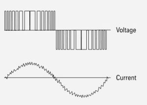
What needs to be said first is that the phrase “active filter,” which one often hears in the audio field, is quite misleading. What it actually is is a switched-mode power supply that first “streamlines” the voltage to DC and then “compiles” a new sine wave from that DC voltage using pulse-width modulation. The modulation frequency ranges from 20 to 40 kHz and on each edge of the pulse, a large amount of further harmonic frequencies is created. Following this “active” part, there inevitably has to be a passive part present to at least partly suppress and filter out the spikes that occur on the sharp edges of the switching transistors.
Passive Filtration
Passive filtration stands firm on verified electrotechnical principles. In short, a range of different connection schemas can be implemented, each with its own advantages and disadvantages and with a set of basic parts. Each of the parts has its quality, efficiency, ideal working range, but also its parasitic properties, which can be only partly minimised in the manufacturing process. Let us have a brief look at the cornerstones of passive filters.
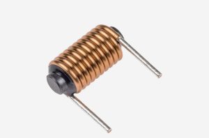
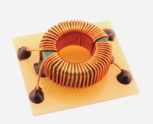
Choke coil (inductance) – accumulates energy in its magnetic circuit thanks to electromagnetic induction. Its parasitic property is internal resistance and redundant heat due to the flowing current. The stronger the wire used for the winding, the lower its internal resistance. The part however also becomes larger in size and more expensive. 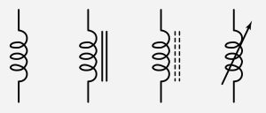
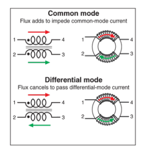
Compensated choke coil – two inductors on a common magnetic circuit. If the magnetic circuit is well designed, it can cause the high frequency spikes of symmetrical interference to cancel each other out.
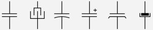
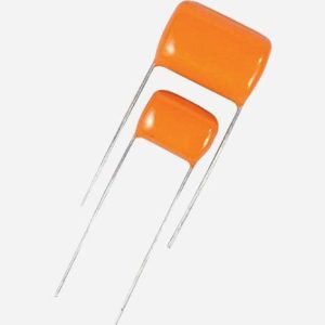
Capacitor (capacitance) – thanks to its capacity (dielectric) accumulates electrical energy. Every real capacitor has also parasitic properties, such as inductance and resistance.
Combining the basic parts, a connection schema working on a certain frequency can be created—such as an integrator, differentiator, LC resonant circuit and so on. Combining the parts in a specific way, we can even exploit some of their parasitic properties.
Interference Transmission in the Power Grid
A power grid is common for everybody in a given power circuit. If anybody’s devices cause interference at their home grid, that interference everybody else at the same transformer station circuit will have at their homes. Interference from all devices adds up. The biggest culprit here are switched-mode power supplies, converters, inverters, fluorescent tubes, which, apart from causing high frequency interference, also deform the sine wave shape (harmonic distortion of power, THD). Without going into details, the trend of increasing interference in the power grid is absolutely clear. Every appliance that causes interference should include an effective filter that eliminates its interference so as not to inhibit another device. The limits of tolerable interference are defined by EMC standards, but in practice, there is simply much more interference in the power grid than the standards allow for.
Why does power grid interference influence audio quality?
The easiest answer is that our hearing is very sensitive, having a range of 1:10-12, one to a trillion. The other significant cause is that high frequency components of interference have the ability to come through the power supply part of a device to the analog part. The more interference there is in the grid, the smaller the distance between signal and noise in the audio output. 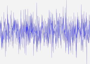
Parasitic high frequency interference occurs on very high frequencies and because of this it acts in a completely different way than power grid voltage with the usual 50 Hz frequency. Parts and schemas that are designed for the usual frequency behave differently on higher frequencies. Mutual capacitance and inductance between conductors or circuit boards both have a much bigger effect; shielding is important. In filters then, it is essential to use the right material and parts designed specifically for one or another part of the high frequency spectrum.
High frequency interference occurs in the grid in the order of millivolts and is modulated on alternating current (230 V/50 Hz). It is not dangerous from the point of its size (except for short-term SURGE/BURST overvoltage), but it is mainly dangerous because of its character, due to which it can very easily influence useful signal, which is what we audiophiles try to avoid as much as possible.
Measuring Power Grid Interference
What needs to be said is that the amount of interference of course changes in time depending on the number and intensity of its sources, location, earthing quality, earthing impedance and power grid impedance. We measure in a given moment, in your surroundings, on the same power circuit, and the result depends on how many sources of interference are active and how much interference they produce.
EMI Line Meter
This is a simple non-calibrated gauge that is fully acceptable for home use. It measures in the frequency range of 10 kHz to 10 MHz. The high frequency interference is displayed in millivolts, the effective value of grid voltage in volts, and the device has an earphone using which the interference can be listened to.
Oscilloscope
Measures voltage values in time. Thanks to an oscilloscope, we can spot a deformation (harmonic distortion) of the sine wave as on the video below, caused predominantly by switched-mode power supplies that draw current from the top of the sine wave only. This deformation is not essential for audio quality. What is much more important here is what appears as tiny fringes, visible mostly on the peaks of the wave. These are the parasitic high frequencies we are most interested in.
More advanced oscilloscopes allow for the calculation of the frequency spectrum using a mathematical function called Fourier’s transformation (FFT) where the deformation due to uneven draw of current (only on the tops of the sine wave) is visible. The first peak is at 50 Hz and it should be the only one. Further peaks in the frequency spectrum are those higher harmonic components we do not wish to have. Comparing them we can calculate THD.
In the video below, there is captured a detail of the bottom peak of a power grid sine wave. The jagged, fringy part is what’s important. If we zoomed the graph in even more, on these fringes, further fringes would become visible, and so on. We will see this when measuring with a spectrum analyzer.
On the output of the F4SX filter, we can see the high frequencies completely suppressed. The energy of the high frequency interference is spread out to a much larger time base. The power supply parts of audio components will easily deal with such a rounded voltage waveform. The wave below is without load. With load (when current is flowing), the shape becomes much smoother.
Spectrum Analyzer
This is a device specifically constructed to analyse the frequency spectrum. For home use, it would be too expensive and because of its sensitivity, it can easily be damaged when not connected professionally. On axis X we can see frequency, on axis Y energy for a given frequency. In the bottom part, we can see the frequency spectrum and its immediate value in time, while the upper part shows a spectrogram that records the average of all measured values.
In the video, we can see power grid interference as captured by the spectrum analyzer. After the first 3 seconds, the output voltage of the F4SX audio filter is measured. We can notice a significant decrease in interference. 50 seconds later, the spectrum analyzer is connected back straight to the power grid and we see a significant increase in interference.
A Final Note
Our F4SX power filter is designed especially for audio components power supply. It suppresses power grid interference significantly and so helps to increase the distance between signal and noise, making the dynamics and microdynamics of music more precise, and emphasizing its spatiality. We will be glad if you visit our listening studio and let your ears convince you…
Newsletter
We'll let you know about our participation in audio shows, new reviews and products, new places to listen to your speakers, or new posts on our blog. We won't spam you.